What Is an Automatic Valve and How Does It Work?
An automatic valve controls the movement of liquids, gases, steam, or other process media without requiring constant manual operation. It responds to a signal, pressure change, temperature reading, flow measurement, or programmed command. Inside, an actuator moves the valve stem or disc. The valve then opens, closes, or adjusts its position.
The principle sounds simple. Real systems are less tidy.
A chemical line may need a valve to maintain steady flow while pressure changes within seconds. A heating system may open a valve when a sensor detects falling temperature. In both cases, the automatic valve must respond accurately, safely, and repeatedly. Poor sizing can cause vibration, delayed control, or excessive energy use. Installation errors can create leaks or unstable operation. These details matter more than attractive product specifications.
Béla G. Lipták, a respected process-control engineer and author, wrote, “The control valve is the final control element in a process control loop.” His statement explains the valve’s practical importance. Sensors may detect a problem, and controllers may calculate a response, but the valve performs the physical correction.
This article examines what an automatic valve is and how it works. It follows the signal from the sensor to the actuator, then into the valve body. It also considers common valve types, operating principles, applications, and selection factors. Some explanations may appear straightforward. However, real performance depends on pressure, temperature, media properties, maintenance, and human judgment. That limitation deserves attention. A valve is not intelligent by itself. It becomes reliable only when the complete control system is designed and tested properly.
What Is an Automatic Valve?
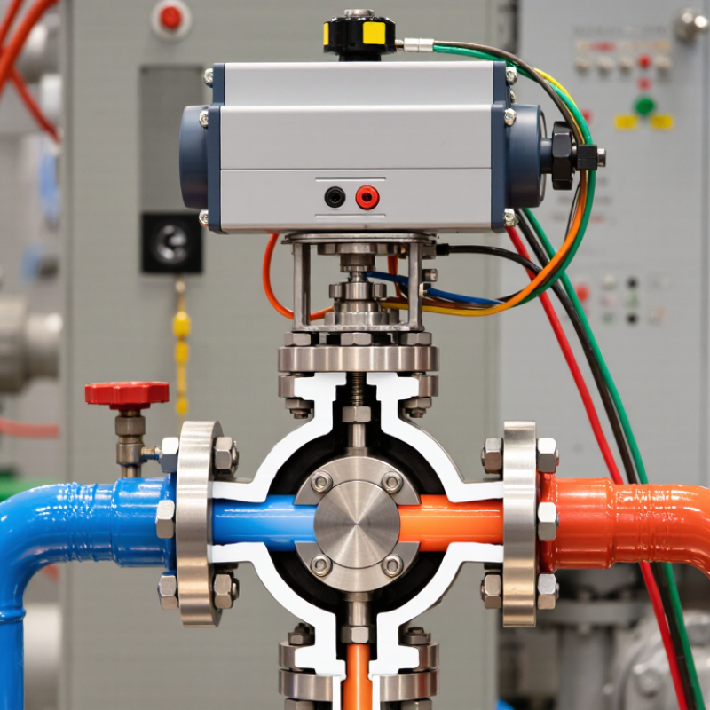
An automatic valve controls fluid or gas flow without requiring constant hand operation. It combines a valve body, actuator, controller, and often a sensor. The controller receives a signal, such as pressure, temperature, or flow rate. The actuator then moves the valve open, closed, or partly open. Small changes matter.
Electric actuators use motors and gears. Pneumatic actuators use compressed air. Hydraulic actuators use pressurized liquid for higher force. In a chilled-water line, a temperature sensor may detect rising heat. The controller responds by opening the valve further. According to a 2024 analysis by Grand View Research, the global industrial valves market was valued at more than 70 billion U.S. dollars in 2023. That scale reflects widespread use in water treatment, energy, manufacturing, and process systems. However, market size does not prove that every installation is reliable.
A properly selected automatic valve should match pressure, temperature, fluid chemistry, flow range, and required response time. Safety planning also matters. Some valves close when power or air fails, while others remain open. The correct choice depends on the process risk. The U.S. Department of Energy’s steam-system guidance emphasizes controlling pressure, temperature, and condensate to reduce operational losses. A valve that moves quickly may still cause water hammer or unstable control. I have seen specifications focus heavily on actuator force while overlooking calibration. That is an imperfect approach. Testing stroke position, leakage, sensor accuracy, and emergency response under real operating conditions remains essential.
What Are the Main Components of an Automatic Valve?
An automatic valve regulates fluid without constant hand operation.
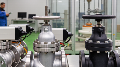
It opens, closes, or adjusts flow after receiving a control signal. The main components include the valve body, actuator, stem, seat, seals, and controller. The body contains the fluid path. The seat creates the closing surface. The stem transfers movement from the actuator to the closure element. In practical installations, stainless steel or coated metal bodies often face heat, pressure, and corrosion. Seal selection still matters. A small leak can become a serious efficiency problem.
The actuator supplies movement.
Electric actuators use a motor and gearbox, while pneumatic actuators use compressed air and a piston or diaphragm. A positioner compares the requested position with actual stem movement. Sensors may monitor pressure, temperature, or flow. The controller then corrects the valve position. A spring-return actuator can move the valve to a safer position after air or power loss. This detail is easy to overlook.
According to MarketsandMarkets, the global industrial valves market may grow from about USD 78 billion in 2024 to more than USD 102 billion by 2029.
That growth reflects wider process automation. Yet market estimates vary by definition and region. Engineers should verify torque, response time, media compatibility, and failure behavior before selection. A valve that fits the pipe may still perform poorly.
How Does an Automatic Valve Work Step by Step?
An automatic valve controls fluid or gas flow without continuous hand operation. Its movement depends on a signal from a sensor, controller, timer, or remote switch. The valve body contains the flow path, while an actuator moves the internal disc, ball, or plug.
The process begins when a sensor detects a condition, such as low pressure or rising temperature. The controller compares that reading with the selected setting. If action is needed, it sends an electrical, pneumatic, or hydraulic signal to the actuator. The actuator then produces movement. A quarter-turn actuator may rotate a ball valve, while a linear actuator may push a gate or stem.
The valve changes position gradually or quickly, depending on its design. A position sensor can confirm whether it is open, closed, or somewhere between. If the feedback does not match the command, the controller may trigger an alarm or stop the process. Some systems close the valve when power or air pressure fails. This response is called fail-safe operation.
Installation details matter. Incorrect flow direction, poor wiring, or weak actuator sizing can cause unstable movement. I have found that a valve may appear functional during a short test but behave poorly under real pressure. Regular checks should examine leaks, response time, seals, connections, and manual override operation. The actual sequence can vary with the medium, pressure, control logic, and safety requirements.
What Types of Automatic Valves Are Commonly Used?
What Is an Automatic Valve and How Does It Work?
Automatic valves regulate fluid or gas without continuous manual operation. A sensor, controller, or pressure signal commands an actuator to open, close, or adjust flow. The actuator may use electricity, compressed air, hydraulic pressure, or the process medium itself. In a factory, this can mean a valve responding within seconds when a pipe temperature rises.
Several automatic valve types are common. Solenoid valves use an electromagnetic coil and suit quick, on-off control in water, air, and fuel systems. Electric motorized valves provide slower, precise movement for heating, cooling, and water treatment. Pneumatic control valves use compressed air and remain popular where fast response and safer operating zones matter. Ball and butterfly valves usually handle isolation or moderate flow control, while globe valves offer finer throttling. Self-operated pressure-control valves work without an external power supply.
According to the International Energy Agency’s 2023 World Energy Outlook, industrial facilities remain major energy consumers, making efficient flow control increasingly important. A 2024 Grand View Research report also identified automation as a key driver in the global industrial valves market. These figures show demand, not guaranteed performance. Valve choice still depends on pressure, temperature, media, cycle frequency, and failure position. A valve can be correctly sized on paper and still hunt, leak, or respond slowly. That is the uncomfortable part. Commissioning tests, maintenance records, and real operating data often reveal problems that calculations miss.
Where Are Automatic Valves Used?
An automatic valve controls fluid or gas without continuous manual operation. An actuator receives a signal from a sensor, timer, controller, or safety system. It then opens, closes, or adjusts the valve position. Electric, pneumatic, and hydraulic actuators are common. The right choice depends on pressure, temperature, flow rate, and response time.
Automatic valves are widely used in water treatment plants. They regulate chemical dosing, filtration, backwashing, and pipeline flow. They also serve heating, ventilation, and air-conditioning systems. The International Energy Agency’s 2024 Global Status Report for Buildings and Construction states that buildings consume about 30% of global final energy. Accurate valve control can reduce unnecessary heating and cooling, although poor commissioning may erase those gains. In irrigation, valves divide water into timed zones. In power generation and process facilities, they isolate equipment and manage high-temperature fluids. The MarketsandMarkets Industrial Valves Market report identifies water, power, oil and gas, and chemical processing as major application sectors. These installations need reliable feedback, not just remote commands.
Tips: Check actuator sizing against real operating pressure. Add position feedback where failure could damage equipment. Test the fail-safe action regularly. A valve that works during normal operation may still respond poorly during a power loss. Review maintenance records, because small leaks often remain unnoticed.