Choosing valve automation and control systems is rarely a simple equipment purchase. It affects safety, process stability, energy use, and maintenance costs. A suitable solution must match the valve type, operating torque, fluid conditions, and control strategy. Small differences matter. A butterfly valve in a water line may need a very different actuator than a severe-service control valve. The right choice begins with verified operating data, not a convenient product catalog.
This guide explains how to evaluate valve automation and control options with practical engineering judgment. It considers pneumatic, electric, and hydraulic actuators, along with positioners, solenoid valves, sensors, communication protocols, and fail-safe requirements. Environmental details also deserve attention. Temperature, corrosion, dust, vibration, and limited access can quickly expose a weak design. Experienced engineers should confirm sizing calculations, interface requirements, maintenance procedures, and applicable industry standards before approval.
No system is perfect. Even experienced teams can overlook a slow response time or an unsuitable fail position. That is why valve automation and control should be assessed as a complete operating system, rather than as separate components. A reliable selection balances initial cost with lifecycle performance, spare-part availability, commissioning support, and operator needs. Site experience often reveals problems that specifications miss. A clear review process helps reduce those surprises, although it cannot remove every risk. Critical applications require documented verification and qualified technical review.

Define valve automation requirements from the process, not from a preferred actuator. Start with the valve’s actual job: isolation, throttling, emergency shutdown, or flow regulation. Record media type, pressure, temperature, pipe size, corrosion risks, and expected operating cycles. A control valve may move continuously, while an isolation valve may operate twice a year. That difference affects actuator sizing and maintenance planning.
Specify the required torque or thrust across the full travel range, including breakaway force and safety margin. Then define the failure position during lost power, signal, or instrument air. Choose pneumatic, electric, or hydraulic operation only after checking available utilities and site conditions. Keep response time measurable. Operating too slowly can disrupt a process, while excessive speed may create water hammer or mechanical stress. The control signal, feedback device, enclosure rating, and communication method must match the control system and installation environment.
Do not treat the datasheet as complete evidence. Field reviews often reveal poor cable routing, limited access, or insufficient space for manual override. A neat specification can still hide these problems. Include ambient temperature, vibration, noise limits, inspection access, and replacement procedures. Verify calculations independently, especially for high-cycle service or large valves. I have seen projects focus on actuator power while overlooking commissioning time and spare parts. That oversight becomes expensive. Leave room for testing, adjustment, and honest review after startup.
Choosing a valve automation system starts with the process, not the actuator. Pneumatic actuators suit fast, repetitive movement and hazardous areas. They also need clean, dry instrument air. The U.S. Department of Energy reports that compressed-air leaks can waste 20–30% of system capacity. That hidden loss can increase operating costs. Check it carefully.
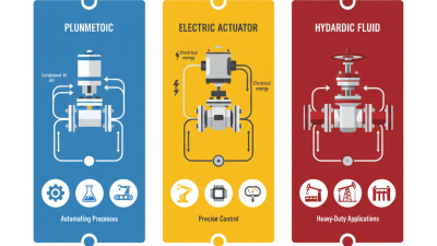
Electric actuators provide accurate positioning, simple wiring, and useful diagnostic feedback. They often fit remote installations with limited air infrastructure. However, motor temperature, duty cycles, and emergency-stop behavior require careful review. Hydraulic actuators deliver high torque in compact packages, but they demand leak control and fluid maintenance. The best technology depends on torque, speed, stroke frequency, ambient conditions, and required failure position. It is rarely perfect.
Control methods deserve equal attention. On-off control is economical for isolation valves, while modulating control supports flow, pressure, and level regulation. Positioners improve response, but poor tuning can create hunting and premature wear. Networked control enables condition monitoring and alarm history. According to the International Energy Agency, motor-driven systems consume about 53% of global electricity, making efficient control strategies important beyond the valve itself. Specify feedback accuracy, communication resilience, cybersecurity controls, and manual override access. Test the complete loop under realistic load conditions. Field experience often exposes gaps that datasheets miss. A practical mistake is choosing the actuator first, then forcing the process to accept it.
| Valve Actuation Technology Comparison | ||||||||||
|---|---|---|---|---|---|---|---|---|---|---|
| Actuation Technology | Energy Source | Valve Motion | Typical Output | Operating Speed | Fail-Safe Options | Positioning Accuracy | Environmental Suitability | Maintenance Considerations | Main Advantages | Common Applications |
| Pneumatic | Compressed air, commonly 3–8 bar (45–120 psi) | Quarter-turn or linear | Torque or thrust; output depends on air pressure and actuator size | Fast; typically suitable for rapid open/close service | Spring-return or double-acting with a dedicated air reservoir | Moderate; improved by positioners and properly sized control valves | Well suited to hazardous areas when correctly configured; requires dry, clean air | Air quality, lubrication, tubing, leaks, and compressor capacity require attention | High speed, simple construction, good safety performance, and low actuator cost | Process isolation, emergency shutdown, chemical processing, water treatment, and packaging |
| Electric | Electrical power; commonly low-voltage DC or single-/three-phase AC | Quarter-turn or linear | Torque or thrust; output is determined by motor, gearbox, and duty rating | Generally slower than pneumatic units, with precise speed control available | Spring-return, supercapacitor, battery, or mechanical fail-safe modules may be available | High; suitable for modulating control with integrated position feedback | Suitable for clean, remote, or utility-limited areas; enclosure and temperature ratings are important | Periodic inspection of gears, seals, limit switches, wiring, and thermal protection | Accurate control, simple installation where compressed air is unavailable, and low operating noise | HVAC, water distribution, district energy, utilities, and automated process lines |
| Hydraulic | Pressurized hydraulic fluid; industrial systems often operate at tens to hundreds of bar | Quarter-turn or linear | Very high torque or thrust in a compact package | Fast response with controllable acceleration and deceleration | Accumulator-based emergency operation or spring-return designs | High when paired with proportional valves and position feedback | Suitable for heavy-duty and high-force service; fluid temperature and leakage must be controlled | Hydraulic-fluid cleanliness, hose condition, seals, filters, and leakage inspections are essential | Very high power density, strong breakaway capability, and reliable operation under heavy loads | Large pipeline valves, oil and gas facilities, hydroelectric equipment, presses, and heavy machinery |
| Electro-Hydraulic | Electrical control combined with hydraulic power | Quarter-turn or linear | High torque or thrust with electronic command capability | Fast to moderate, depending on the hydraulic power unit and valve sizing | Accumulator, spring-return, or stored-energy systems | High; supports remote monitoring and closed-loop positioning | Useful where electrical control and high mechanical force are both required | Combines electrical diagnostics with hydraulic maintenance requirements | High force, flexible control, and dependable emergency operation | Remote pipeline stations, offshore facilities, turbines, and critical shutdown systems |
| Manual with Position Monitoring | Operator effort; electrical power may be used only for switches or transmitters | Quarter-turn or linear | Limited by handwheel, lever, chainwheel, or gearbox capability | Dependent on operator access and mechanical gearing | No automatic fail-safe action; valve remains in its last manually selected position | Low to moderate; position switches can confirm open or closed status | Useful in remote-power or low-duty locations, subject to safe operator access | Simple mechanical inspection and periodic lubrication | Low capital cost, simple operation, and minimal infrastructure | Low-frequency isolation, maintenance bypasses, utility lines, and small installations |
| Valve Control Method Comparison | |||||||
|---|---|---|---|---|---|---|---|
| Control Method | Command Signal | Typical Function | Position Feedback | Response and Accuracy | Primary Benefits | Key Limitations | Best-Fit Applications |
| On/Off Control | Discrete electrical signal, solenoid signal, or local command | Fully open or fully closed operation | Limit switches, proximity switches, or actuator indicators | Fast and simple; not intended for continuous throttling | Low complexity, easy troubleshooting, and reliable isolation | Cannot accurately regulate flow, pressure, or level between end positions | Isolation, safety shutdown, drain systems, and batch sequencing |
| Modulating Control | Analog signal such as 4–20 mA, 0–10 V, or a digital setpoint | Continuous adjustment of valve position | Position transmitter, potentiometer, encoder, or digital position sensor | Good accuracy when actuator, valve, and positioner are correctly sized | Regulates flow, pressure, temperature, level, or process composition | Higher cost and greater sensitivity to sizing, hysteresis, deadband, and process conditions | Process control loops, utilities, heat exchange, and flow balancing |
| PID Closed-Loop Control | Controller output based on setpoint, process variable, and tuning parameters | Automatic correction of process deviations | Process transmitter plus valve position feedback where required | High control performance when loop tuning and valve sizing are appropriate | Maintains stable process conditions and reduces operator intervention | Poor tuning, sensor faults, or excessive valve friction can cause oscillation | Temperature, pressure, flow, level, and combustion control |
| Fieldbus or Industrial Ethernet | Digital network communication with diagnostics and parameter data | Remote command, configuration, monitoring, and predictive diagnostics | Digital feedback, travel counters, torque data, and diagnostic status | Accurate and information-rich; network design affects availability | Reduced wiring, centralized diagnostics, and easier asset management | Requires compatible network architecture, cybersecurity practices, and trained personnel | Large plants, distributed equipment, process automation, and condition monitoring |
| Safety Instrumented Control | Independently verified safety logic and emergency trip signal | Moves the valve to a defined safe state during a hazardous event | Redundant feedback, partial-stroke testing, and proof-test information | Designed for defined safety integrity and predictable response | Risk reduction, emergency isolation, and documented safety performance | Requires formal hazard analysis, validation, proof testing, and lifecycle management | 燃ammable, toxic, high-pressure, and other high-consequence process services |
Valve automation should be selected around the process, not only the valve size. Start by recording fluid type, temperature, pressure, flow direction, and cycle frequency. A clean-water service may tolerate a simple actuator. Hot, corrosive, or abrasive media demand better sealing, materials, and protection. Check the valve’s torque or thrust across its full stroke. Do not rely on the starting value alone. It may rise sharply near closure.
Then match the control system with existing equipment. Confirm power supply, signal type, communication protocol, enclosure rating, and installation space. A pneumatic actuator needs dependable air quality and pressure. An electric actuator needs suitable voltage, duty rating, and heat management. The fail position deserves careful review. Closing on power loss can protect a line, but opening may prevent dangerous pressure buildup. Process safety should guide this choice. Test feedback accuracy, response time, and manual override access before approval. Small delays can destabilize a control loop.
Site conditions are easy to underestimate. Dust, washdown water, vibration, freezing temperatures, and limited access can shorten service life. Ask maintenance staff how often adjustment and inspection are realistic. A system requiring perfect calibration every week may fail in a busy plant. Fit matters. Field reviews often reveal awkward cable routes and unreachable handwheels. A neat specification can still mislead. Simulate normal, start-up, shutdown, and fault conditions with the actual equipment. Record uncertain assumptions and revisit them during commissioning. Compatibility on paper is not always compatibility in operation.
Preliminary valve automation selection should consider the process medium, operating temperature, pressure, required control accuracy, enclosure protection, and available power or instrument air. The temperature values shown are representative engineering conditions: chilled water at approximately 5°C, hot water at approximately 90°C, saturated steam at 10 bar at approximately 184°C, and thermal oil at approximately 300°C. Final actuator, valve, seal, and control-system selection must be verified against the equipment manufacturer’s certified ratings.
Choosing valve automation starts with the hazard, not the actuator. In field assessments, I record fluid temperature, pressure, toxicity, flow direction, and failure consequences. A valve controlling hot steam needs different safeguards from one handling clean water. Define the safe state clearly: fail-open, fail-closed, or remain in place. This decision should follow a documented risk assessment. Never rely on habit.
Safety includes emergency shutdown, position feedback, torque limits, and manual override access. Verify that sensors still report accurately during power loss. Reliability depends on duty cycles, enclosure protection, corrosion resistance, and backup power availability. Ask for tested performance data, not attractive claims. A system that works in a workshop may struggle beside salt spray, vibration, or dust. I have seen maintenance plans fail because nobody checked cable access. Small details matter. Not always.
Maintenance should be practical under real site conditions. Can technicians isolate the valve safely? Are diagnostic records understandable? Are spare parts, calibration tools, and training available locally? Set inspection intervals from operating data, then revise them after failures or near misses. Regulatory requirements vary by process and jurisdiction, so map the system to applicable safety, electrical, pressure, and emissions rules. Keep approval documents and test records traceable. I would challenge the original specification yearly; assumptions age faster than equipment. That review may reveal a cheaper option, or a dangerous gap. Check twice.
Selecting a valve automation and control system starts with the process, not the product. Define pressure, temperature, flow rate, valve torque, and failure position before comparing technical options. I have seen projects stall because engineers checked the actuator but overlooked manual override access. A reliable selection also considers hazardous areas, environmental exposure, maintenance space, and available control signals. Small errors compound. Record every assumption and ask an independent engineer to challenge unclear data.
Integrate the final control system with the process drawings, wiring schedules, control logic, and safety requirements. Confirm signal ranges, response times, feedback accuracy, and communication behavior during power loss. The valve should move predictably, not merely respond during a desk review. Perform a factory acceptance test with simulated commands and fault conditions. Then repeat critical checks during site commissioning, using real cables and operating pressures. Do not hide weak results. A failed test is useful evidence, although it may expose poor planning.
Tips: Create a valve-by-valve test sheet with expected position, travel time, alarm status, and fail action. Mark each result immediately. Test local and remote control separately. Check partial-stroke behavior where applicable. Keep photographs of wiring terminals and instrument displays for traceability. One practical improvement is adding a short re-test after control logic changes. It feels repetitive. It prevents surprises. Review the final records with operations staff, because maintainers often notice access or reset problems that design teams miss.